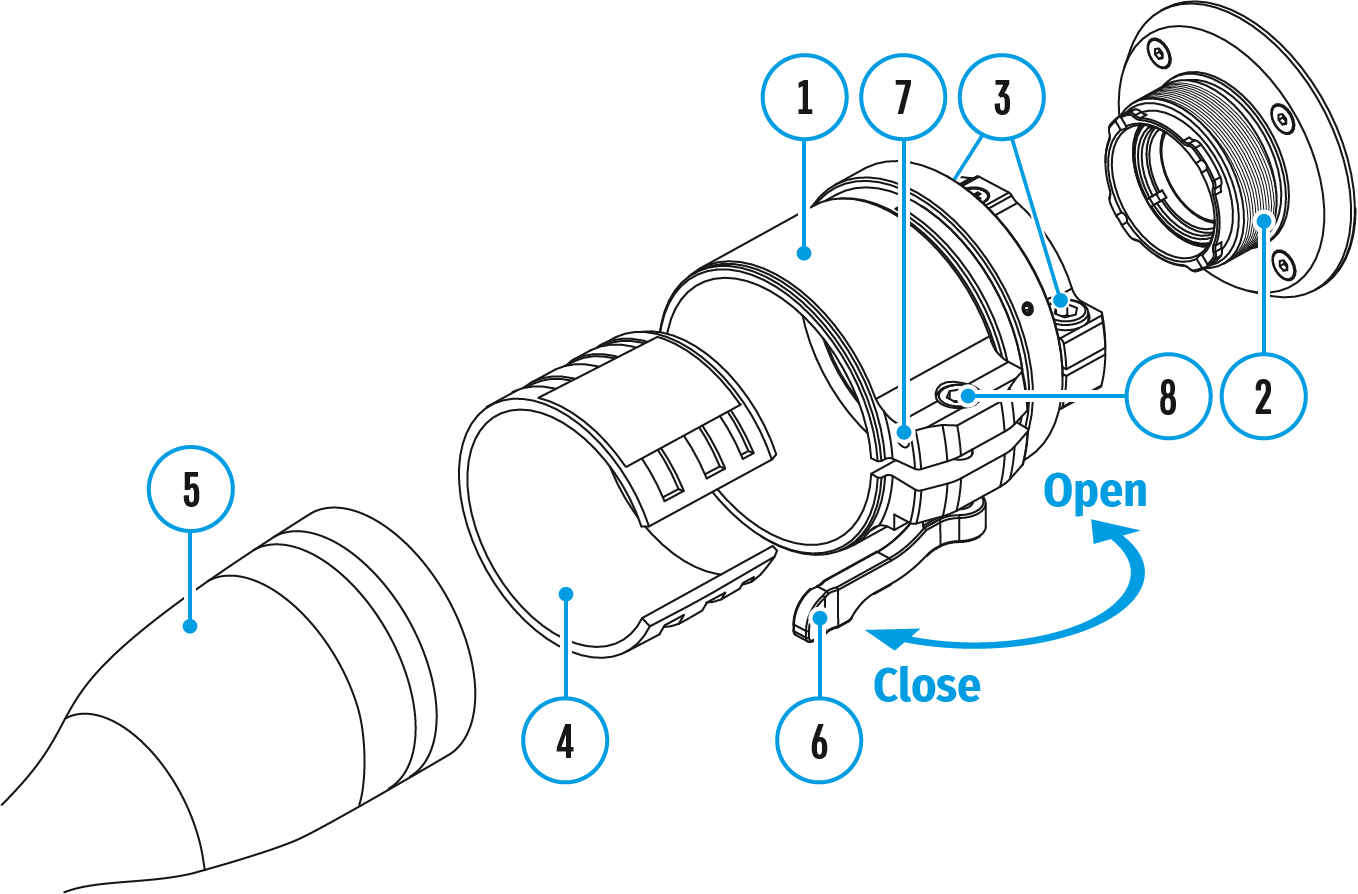
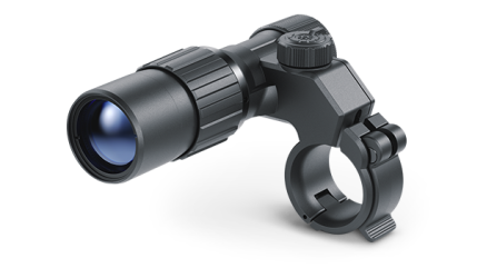
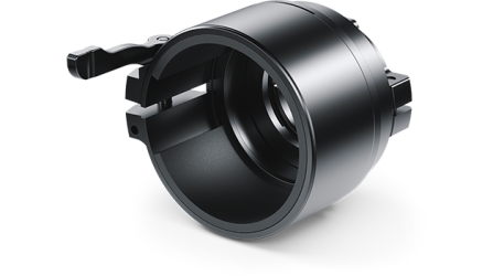
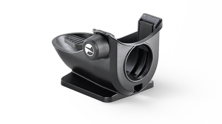
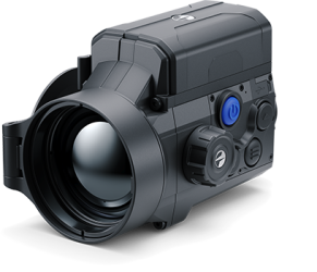
1. Remove the protective cover from the eyepiece of the front lens mounted module.
2. Select the Ring Adapter (1) with the insert (4) of the desired diameter depending on the outer diameter of the lens of your optical device (5) (see Table). The designation 42 mm / 50 mm / 56 mm in the name of the adapter means the lens diameter of the optical device.
3. Screw together the Ring Adapter (1) and the front lens mounted module along the threads of the mounting area (2) until it stops. Then untighten a little (no more than one turn) so that the lever (6) is on the right side (see Figure).
4. Evenly tighten the screws (3) until the ball joint grips in the Ring Adapter (1).
5. Apply 2-3 strips of double-sided tape to the outer surface of the insert of your choice (4).
6. Push the insert (4) of your choice into the Ring Adapter (1) until it stops.
7. Move the lever (6) to the OPEN position.
8. Before installing the Ring Adapter (1) onto the optical device, it is recommended to degrease the lens body of the optical device (5).
9. Mount the Ring Adapter with the insert onto the lens of the daylight optical device (5) as far as it will go.
10. If the Ring Adapter (1) with the insert (4) selected according to the table cannot be mounted onto the lens (5), follow the steps below:
- Loosen the locking screw (7) with a 2mm Allen key.
- Untighten the screw (8) with a hex wrench (S = 4mm) until the Ring Adaptor with the insert can be mounted onto the lens (5).
11. Move the lever (6) from its initial OPEN position to the CLOSE position.
12. Loosen the locking screw (7) with a 2mm Allen key, if it hasn’t been done before.
13. Tighten the screw (8) with an Allen key (S = 4mm). The clamping force should be 1.5-2 Nm (use a torque screwdriver) to ensure the lever is correctly tightened (6), while the Ring Adapter with the front lens mounted module should not move relative to the body of the optical device (5). If necessary, tighten or loosen the screw (8) to operate the lever (6) in the best way possible.
14. Tighten the locking screw (7) as far as it will go.
15. Turn on the front lens mounted module.
16. Align the image center on the display with the image center of the optical scope by carefully tilting the front lens mounted module.
17. Align top and bottom display boundaries parallel to the horizontal axis by turning the front lens mounted module clockwise or counterclockwise.
18. Having reached the best possible position of the front lens mounted module, tighten the two screws (3). The clamping force should be 6.5-7.5 N·m (use a torque screwdriver to check).
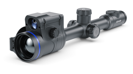
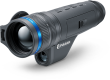
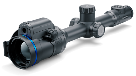
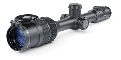
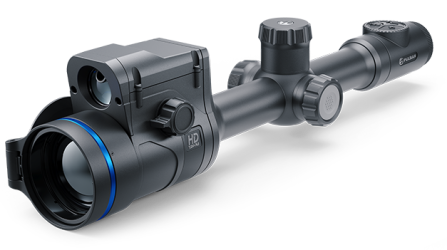 Thermion 2 LRF XL50
Thermal Imaging Riflescope
Thermion 2 LRF XL50
Thermal Imaging Riflescope
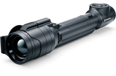
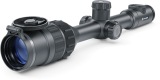
 Thermion 2 LRF
Thermal Imaging Riflescopes
Thermion 2 LRF
Thermal Imaging Riflescopes
 Talion
Thermal Imaging Riflescopes
Talion
Thermal Imaging Riflescopes
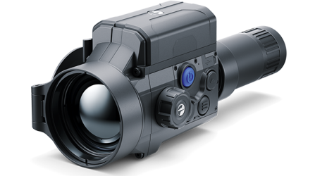
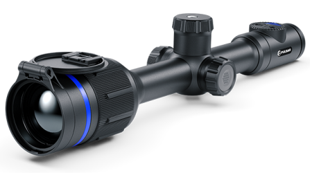 Thermion 2
Thermal Imaging Riflescopes
Thermion 2
Thermal Imaging Riflescopes
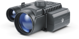
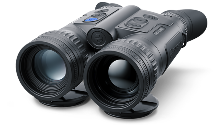
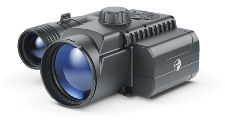
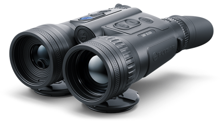 Merger LRF XL50
Thermal Imaging Binoculars
Merger LRF XL50
Thermal Imaging Binoculars
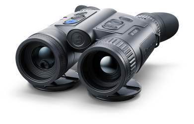
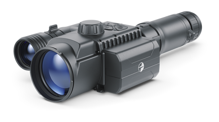
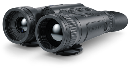 Merger LRF XP50
Thermal Imaging Binoculars
New
Merger LRF XP50
Thermal Imaging Binoculars
New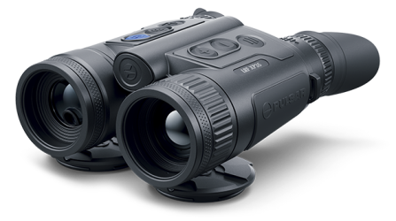 Merger LRF XP35
Thermal Imaging Binoculars
Merger LRF XP35
Thermal Imaging Binoculars
 Merger LRF XQ35
Thermal Imaging Binoculars
New
Merger LRF XQ35
Thermal Imaging Binoculars
New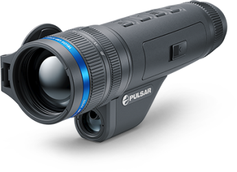 Telos
Thermal Imaging Monoculars
Telos
Thermal Imaging Monoculars
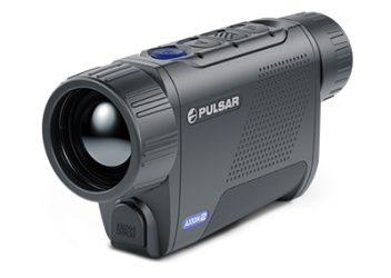
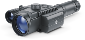
 Axion 2 LRF
Thermal Imaging Monoculars
Axion 2 LRF
Thermal Imaging Monoculars
 Axion 2
Thermal Imaging Monoculars
New
Axion 2
Thermal Imaging Monoculars
New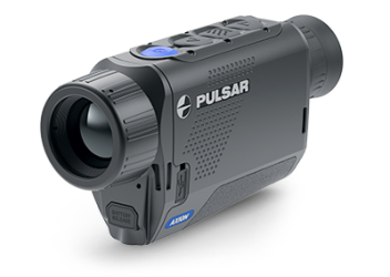 Axion XQ30 PRO
Thermal Imaging Monoculars
Axion XQ30 PRO
Thermal Imaging Monoculars
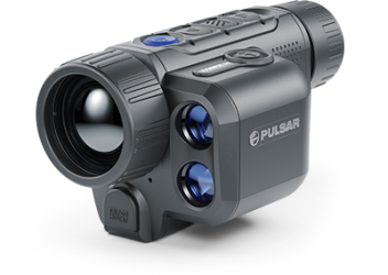
 Krypton 2
Thermal Imaging Monocular
Krypton 2
Thermal Imaging Monocular
 Axion XM30F
Thermal Imaging Monoculars
Axion XM30F
Thermal Imaging Monoculars
 Pulsar Digex-XS
External Infrared Illuminators
Pulsar Digex-XS
External Infrared Illuminators
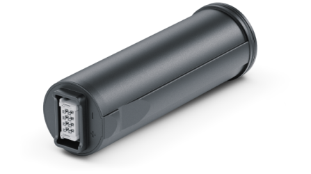 APS Batteries
Battery Packs
APS Batteries
Battery Packs
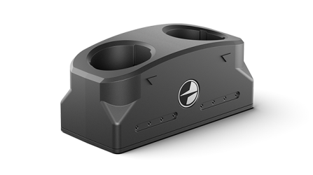 APS Chargers
Battery Chargers
APS Chargers
Battery Chargers
 IPS Batteries
Battery Packs
IPS Batteries
Battery Packs
 IPS Battery Charger
Battery Charger
IPS Battery Charger
Battery Charger
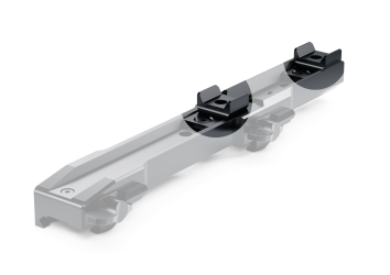
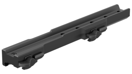 Rifle Mounts
for Pulsar Riflescopes
Rifle Mounts
for Pulsar Riflescopes
 H7 Spacers
Repair Kits
New
H7 Spacers
Repair Kits
New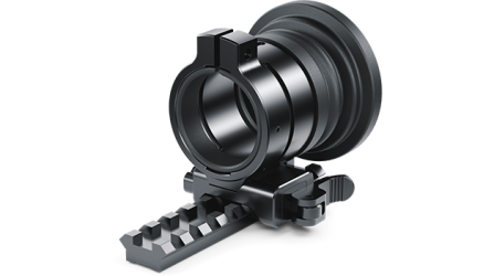 PSP-V Weaver Rail Adapter
Adapter
PSP-V Weaver Rail Adapter
Adapter
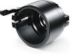
 PSP Ring Adapters
Adapters
New
PSP Ring Adapters
Adapters
New PSP-B Ring Adapters
Ring Adapters
PSP-B Ring Adapters
Ring Adapters
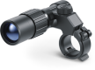
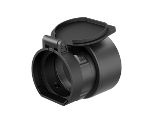 FN Adapters
Cover Ring Adapters
FN Adapters
Cover Ring Adapters
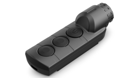 Remote Controls
for digital devices and thermal imagers
Remote Controls
for digital devices and thermal imagers
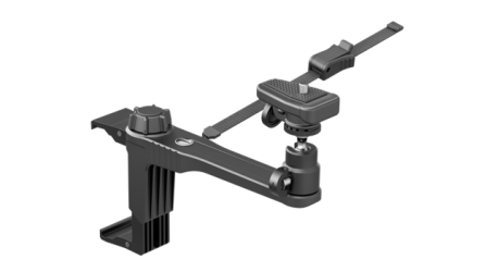
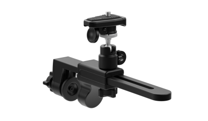 C-Clamp Mount
Pulsar Accessories
C-Clamp Mount
Pulsar Accessories
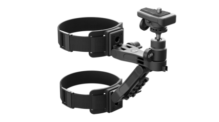 Tree mount
Pulsar Accessories
Tree mount
Pulsar Accessories
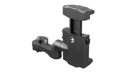
 Window Frame Mount
Pulsar Accessories
Window Frame Mount
Pulsar Accessories
 Helion Flip-Up Phone Mount
Pulsar Accessories
Helion Flip-Up Phone Mount
Pulsar Accessories
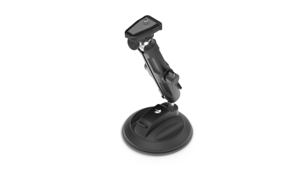 Flat Glass Mount
Pulsar Accessories
Flat Glass Mount
Pulsar Accessories
 Neck Straps
Accessories
New
Neck Straps
Accessories
New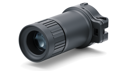 Monocular Pulsar 3x20 B
Accessories
Monocular Pulsar 3x20 B
Accessories
 Thermal Zeroing Targets
Accessories
Thermal Zeroing Targets
Accessories
 Telos LRF Tripod Adapter
Pulsar Accessories
Telos LRF Tripod Adapter
Pulsar Accessories


 English
 German
 French
 Spanish
 Italiano
 English
 Lietuvių