THE MAIN PARAMETERS OF THERMAL IMAGING DEVICES
The thermal sensor (microbolometer) resolution is an important parameter for assessing sensor quality. It is the number of sensitive elements (pixels), constituting the sensor. Sensors with a large number of pixels can produce a more detailed image of an object.
Standard sizes for thermal imaging sensors are:
| Sensor resolution |
Aspect ratio |
| 160х120 |
4:3 |
| 320х240 |
4:3 |
| 384х288 |
4:3 |
| 640х480 |
4:3 |
| 1024х768 |
4:3 |
Pixel pitch
Pixel pitch is the distance between the centres of two pixels of a microbolometer. In thermal imaging sensors, it is measured in microns (µm).
Fill Factor
Fill factor is the ratio of sensitive surface of all pixels to the total area of pixels. Sensors with a higher fill factor can absorb a larger amount of energy.
Magnification
The magnification value shows how many times the observed image (with the help of the optic device) is larger compared to the object observed with a naked eye. Unit of measure is magnifying power (“x” symbol, e.g. 2x - “2x power”).
For thermal imaging units typical values are in the range of 1x - 5x, since the main task of night vision units is detection and recognition of objects in low light conditions or unfavourable weather conditions. Increasing the magnification of thermal imaging units leads to a considerable decrease in lens speed (or relative aperture) and this results in a significant drop of contrast in respect to the background. The decrease of lens speed with the magnification increase can be compensated by increasing the light aperture but this, in turn, will lead to an overall increase of the unit’s dimensions, weight and complication of optics design. All these factors reduce the comfort of use of the units and raise the price of thermal imagers significantly.
Comfort is extremely important for thermal imaging riflescopes because the shooter has to hold it with the weapon in their hands. Large magnification also leads to difficulties in target search and tracking, especially if the target is moving, since magnification increase leads to a decrease in the field of view.
Magnification is defined by the focal length of the objective lens and eyepiece and by the scaling coefficient (K) that is equal to the ratio of the physical sizes (diagonals) of the display and sensor:
Where:
f objective lens – the focal length of the objective lens
f eyepiece – the focal length of the eyepiece
L display – the diagonal size of the display
L sensor – the diagonal size of the sensor
Magnification Dependencies:
The higher the focal length of the objective lens, display size, the higher magnification.
The higher the focal length of the eyepiece, sensor size, the smaller magnification.
Field of View
The field of view defines the size of space that can be viewed through the optical device at a defined distance. Field of view is usually given in degrees (angular field of view is shown below in the image as 2Ѡ) or in metres for a specific distance (M) (usually 100M) to theobserved object (linear field of view is shown as A in the image).
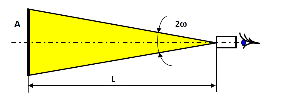
The field of view of a digital night vision device is defined by the focal length of the objective lens (f objective lens) and the physical size of the sensor (B). For calculation purposes, they usually use the width (horizontal size) as the physical size of the sensor and in the result, they get the horizontal field of view:

If vertical sensor size or diagonal sensor size are known it is possible to calculate the vertical or diagonal field of view similarly.
The wider the field of view, the more comfortable observation as there is no need to move the device constantly to view the necessary part or space.
It is important to understand that field of view is inversely proportional to magnification – meaning that when magnification increases field of view shrinks. This is one of the reasons why infrared systems (thermal imagers in particular) with high magnification are not manufactured. At the same time, it is important to understand that an increase in the field of view leads to a decrease in detection and recognition range.
Field of View Dependency:
The larger sensor size or smaller focal length of the objective lens, the wider angular field of view.
Frame Rate
The frame rate is one of the main characteristics of a thermal imaging device. From the user’s point of view, it is the number of frames displayed on the screen in one second. This is usually measured in Hertz (Hz) where 1Hz is equal to 1 frame per second. The higher the frame rate value, the less visible the effect of lagging of image produced by thermal imager in respect to the real scene. Observation of dynamic scenes with a thermal imager that has 9 fps rate shows a blurry image and object movements may seem laggy and “jerky”. On the contrary, the higher the frame rate, the smoother will be the rendering of dynamic scenes.
Resolution & Factors that Influence Resolution
Resolution is defined by the parameters of a device’s optical elements, sensor, display, quality of electronic circuits and also by the applied software algorithms. The resolution of a thermal imaging device (resolving power) is a complex value, that consists of thermal resolution and spatial resolution. Let’s look at each of these separately:
- Thermal resolution (NETD – Noise Equivalent Temperature Difference)
In laymans terms this is the sensitivity of the device or the minimal detectable temperature difference and it is a ratio of object’s signal to background’s signal that takes into account the noise signal from the thermal sensor of a thermal imager. Good thermal resolution means that a thermal imager can show an object with a certain temperature on the background with a very close temperature, and the smaller difference between the temperatures of object and background that can be displayed, the higher thermal resolution.
- Spatial Resolution
Spatial resolution characterizes the ability of devices to show two closely located points or lines separately. In technical specifications of a device, this parameter can be specified as “resolution”, “resolution limit”, “maximum resolution” which is the same.
Often the device resolution is determined by the spatial resolution of the thermal sensor (microbolometer) because the spatial resolution of the optics far exceeds that of the thermal sensor.
As a rule, spatial resolution is defined in lines per millimetre but it can be specified in angular units (seconds or minutes). The higher the value of resolution in lines per millimetre, the higher resolution. The higher resolution of the device, the clearer the image seen by the observer.
For measuring resolution a special piece of equipment is used called a collimator, it creates an imitation image of a test-chart – thermal line test target. Looking at the test chart through optic device one can judge the resolution of thermal imager – the smaller the lines that are separelty visible the higher resolution of the device.
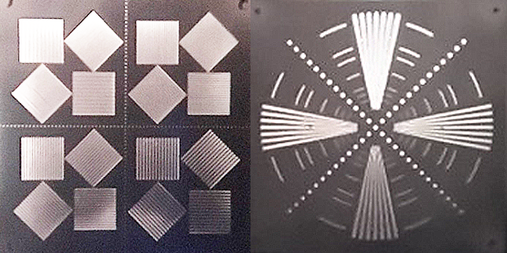 |
| Image: Various types of thermal imaging test charts (thermal imaging view) |
The resolution also depends on the resolution of the objective lens and eyepiece. The objective lens creates an image of an observed object on the focal plane array and in the case where the resolution of the objective lens is low, further improvement of the unit’s resolution is impossible. In the same way, a low-quality eyepiece can “spoil” the clearest image produced by the device and its components on the display.
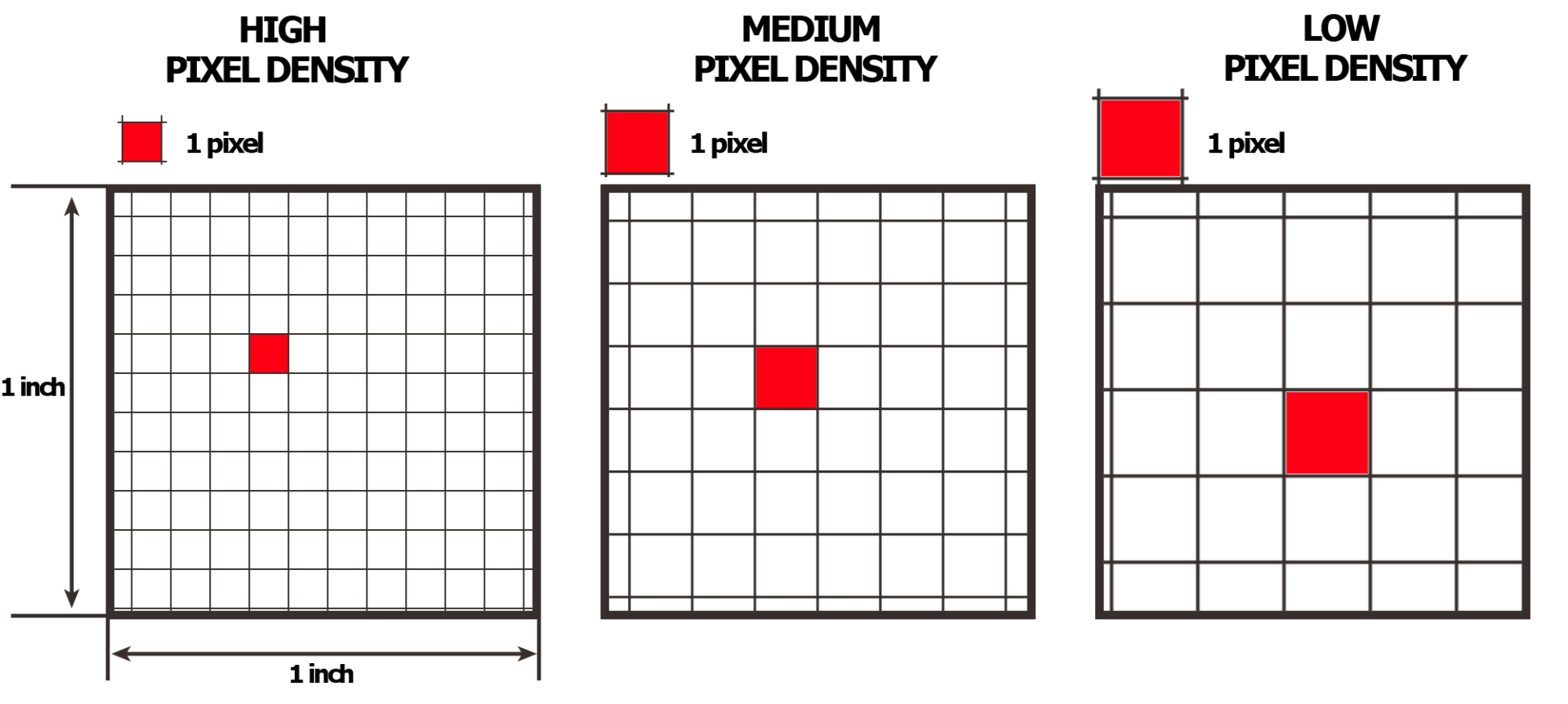
The spatial resolution of the device also depends on the display’s parameters. As is the case of the sensor, the resolution of the display is shown similarly - the number of pixels (horizontal x vertical) and their size. Pixel density is characterized by such value as PPI (pixel per inch) – this value shows the number of pixels in a one-inch area.
Thermal sensor parameters greatly influence the resolution of the device. Primarily the resolution of thermal sensor (microbolometer) is the total number of pixels (usually shown as horizontal number of pixels x vertical number of pixels) and pixel pitch. These two criteria provide the main ground for assessing resolution.
Thermal imagers may use different algorithms for signal processing that can influence the overall resolution of the unit. Primarily the talk is about “digital zooming” when the image created by the focal plane array is processed and transferred to the display with magnification. In this case, a slight decrease in overall resolution takes place. A similar effect can be observed in digital photo cameras when digital zoom is used.
Apart from the described above factors, some additional factors that can reduce the resolution should be mentioned. Primarily these are various types of “noise” distorting useful signal and in the final run worsening image quality. The following types of noise can be distinguished:
Dark Current Noise – the main reason for the occurrence of this type of noise is thermionic electron emission (spontaneous emission of electrons that result in the heating of the thermal sensor material). The lower the temperature the lower the dark current signal i.e. lower noise, and precisely for this purpose shutter and microbolometer calibration is used.
Read Noise - When the signal stored in one pixel is taken out of the sensor, turned into voltage and amplified, additional noise appears in each element, and this noise is called read noise.
Various software algorithms often called noise suppression algorithms are applied to combat noise.
Aside from the noise, resolution can be greatly decreased by electronic interference that appears because of mistakes in the design of the unit (placement of boards and wires inside the unit) or because of mistakes in the board tracing (position of conducting paths and quality of shielding layers). Electronic interference can also be caused by mistakes in electronic circuits of the unit such as the wrong selection of the elements for making the filters inside the power circuits. Thus electronic circuitry design, software development for signal processing and board tracing are important tasks in designing of thermal imaging devices.
Resolution Dependency:
The greater the number of pixels and smaller their size of the thermal sensor, the better resolution.
The statement is true when compared thermal sensors are of the same physical size. Thermal sensors with a greater pixel density have a better resolution.
Observation Range
The quoted observation range of a thermal imaging device depends on a combination of a large number of internal factors (sensor parameters, optics and electronics) and external conditions (various characteristics of the observed object, background, atmosphere clarity, etc.).
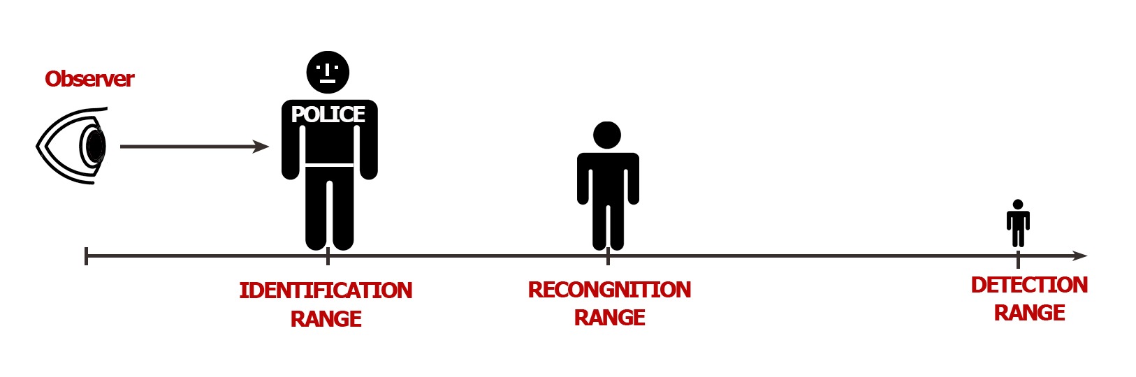
Observation range is typically divided into detection range, recognition range and identification range. Each of these ranges is defined by Johnson’s criteria according to which the observation range is directly connected to temperature and spatial resolution.
To fully explain this topic, it is necessary to introduce the notion of the critical size of an observed object. The critical size is the size which serves as a base for the object image analysis for finding its characteristic geometric features. For instance, the critical size of a wild boar, roe deer or human is the height of its body.
Detection Range
The distance where the critical size of an observed object can be fit in two or more pixels of a thermal imaging sensor is called the detection range. Detection only means that the object is visible at a certain distance but does not give any information about its characteristics (i.e. the type of object cannot be determined).
Recognition Range
The recognition of an object means that the type of object can be defined. This means that observer can discern what is being observed i.e. human, animal, car, etc. It is considered that recognition is possible when the critical size of an object can fit into at least 6 pixels of the sensor.
Identification Range
From the hunter’s point of view, the most useful range is the identification range. Identification means that the observer can evaluate not only the type of object but also its characteristic features (e.g. wild boar male 1.2 m long and 0.7 m high) For this condition to happen the critical size of an object should fit in at least 12 pixels of the sensor.
It is important to understand that in all listed cases there is a 50% probability of detection, recognition or identification of the specified object. The more pixels covered by the critical size of an object the higher probability of detection recognition or identification.
Eye Relief
Eye relief is the distance from the external surface of last eyepiece lens to the surface of the observer’s eye where an observed image is the most optimal (maximal field of view with minimal distortions). This parameter is very important for riflescopes, where the eye relief has to be not less than 50mm (80-100mm is optimal). Such a high value of eye relief is necessary to avoid a shooter becoming injured due to recoil when taking a shot. As a rule, in night vision and thermal imaging units’ the eye relief is equal to the length of eye-cup which is necessary to camouflage the light emitted by the display.
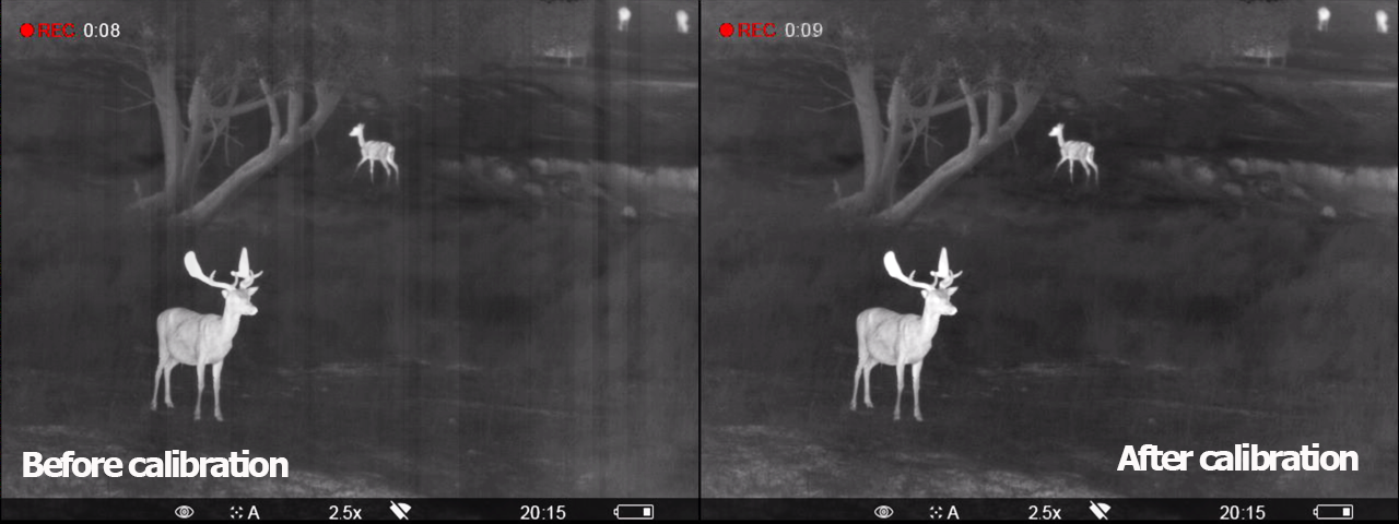
Thermal Sensor Calibration
Calibration of a thermal imaging device can be divided into factory calibration and user-defined calibration. The manufacturing process of thermal imaging devices using uncooled microbolometers (thermal sensors) needs a factory calibration of the device (objective lens paired with sensor) that requires the use of special equipment.
Factory calibration does not eliminate the necessity of a user-defined calibration during observation. During the device’s operation, a user-defined calibration can be done with the help of an internal shutter covering sensor or lens cap covering the objective lens and sensor. It is worth mentioning that calibration with the help of lens cap provides the best result because it additionally corrects the image flaws caused by parasitic emission coming from the device’s parts and lenses. Some devices are calibrated using software without using shutter or lens cap.
User-defined calibration is required due to the thermal sensor heating up unevenly during use and this introduces noise, causing the unit to render the observed scene incorrectly. During the process of calibration different parts of the sensor are evaluated and calculations are carried out to level the signal resulting in the device producing a correct image.
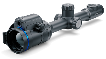
 Thermion 2 LRF XL50
Thermal Imaging Riflescope
Thermion 2 LRF XL50
Thermal Imaging Riflescope
 Thermion 2 LRF
Thermal Imaging Riflescopes
Thermion 2 LRF
Thermal Imaging Riflescopes
 Talion
Thermal Imaging Riflescopes
Talion
Thermal Imaging Riflescopes
 Thermion 2
Thermal Imaging Riflescopes
Thermion 2
Thermal Imaging Riflescopes
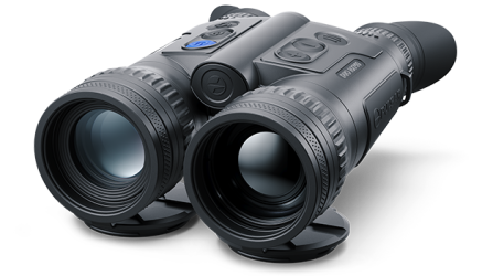
 Merger LRF XL50
Thermal Imaging Binoculars
Merger LRF XL50
Thermal Imaging Binoculars
 Merger LRF XP50
Thermal Imaging Binoculars
New
Merger LRF XP50
Thermal Imaging Binoculars
New Merger LRF XP35
Thermal Imaging Binoculars
Merger LRF XP35
Thermal Imaging Binoculars
 Merger LRF XQ35
Thermal Imaging Binoculars
New
Merger LRF XQ35
Thermal Imaging Binoculars
New Telos
Thermal Imaging Monoculars
Telos
Thermal Imaging Monoculars
 Axion 2 LRF
Thermal Imaging Monoculars
Axion 2 LRF
Thermal Imaging Monoculars
 Axion 2
Thermal Imaging Monoculars
New
Axion 2
Thermal Imaging Monoculars
New Axion XQ30 PRO
Thermal Imaging Monoculars
Axion XQ30 PRO
Thermal Imaging Monoculars
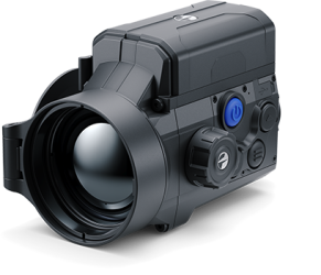
 Krypton 2
Thermal Imaging Monocular
Krypton 2
Thermal Imaging Monocular
 Axion XM30F
Thermal Imaging Monoculars
Axion XM30F
Thermal Imaging Monoculars
 Pulsar Digex-XS
External Infrared Illuminators
Pulsar Digex-XS
External Infrared Illuminators
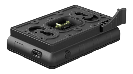
 APS Batteries
Battery Packs
APS Batteries
Battery Packs
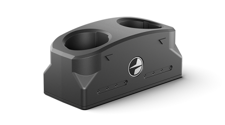 APS Chargers
Battery Chargers
APS Chargers
Battery Chargers
 IPS Batteries
Battery Packs
IPS Batteries
Battery Packs
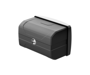
 IPS Battery Charger
Battery Charger
IPS Battery Charger
Battery Charger
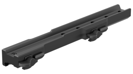 Rifle Mounts
for Pulsar Riflescopes
Rifle Mounts
for Pulsar Riflescopes
 H7 Spacers
Repair Kits
New
H7 Spacers
Repair Kits
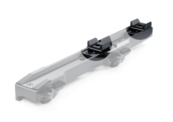
New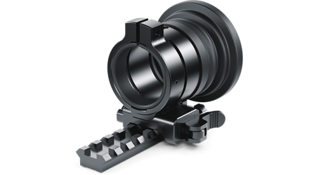 PSP-V Weaver Rail Adapter
Adapter
PSP-V Weaver Rail Adapter
Adapter
 PSP Ring Adapters
Adapters
New
PSP Ring Adapters
Adapters
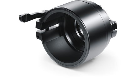
New PSP-B Ring Adapters
Ring Adapters
PSP-B Ring Adapters
Ring Adapters
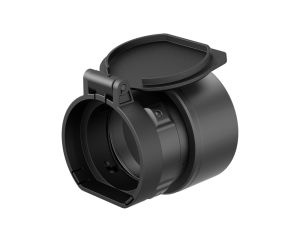 FN Adapters
Cover Ring Adapters
FN Adapters
Cover Ring Adapters
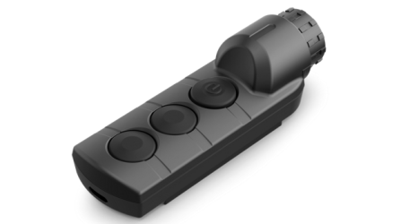 Remote Controls
for digital devices and thermal imagers
Remote Controls
for digital devices and thermal imagers
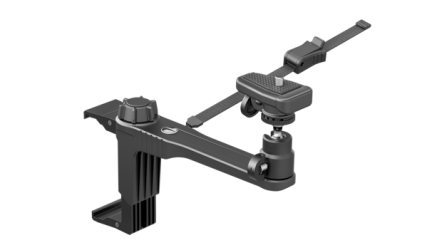
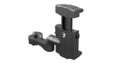
 C-Clamp Mount
Pulsar Accessories
C-Clamp Mount
Pulsar Accessories
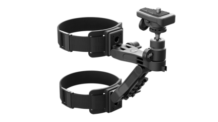 Tree mount
Pulsar Accessories
Tree mount
Pulsar Accessories
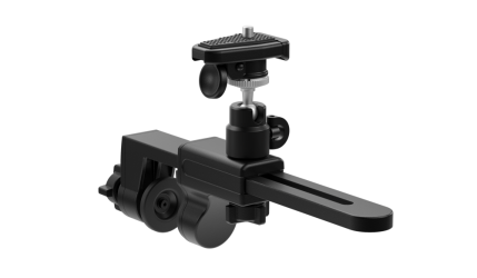
 Window Frame Mount
Pulsar Accessories
Window Frame Mount
Pulsar Accessories
 Helion Flip-Up Phone Mount
Pulsar Accessories
Helion Flip-Up Phone Mount
Pulsar Accessories
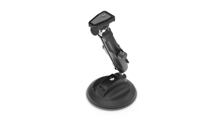 Flat Glass Mount
Pulsar Accessories
Flat Glass Mount
Pulsar Accessories
 Neck Straps
Accessories
New
Neck Straps
Accessories
New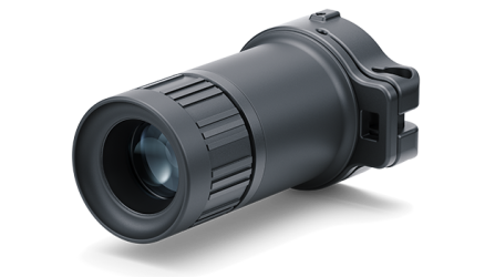 Monocular Pulsar 3x20 B
Accessories
Monocular Pulsar 3x20 B
Accessories
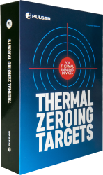 Thermal Zeroing Targets
Accessories
Thermal Zeroing Targets
Accessories
 Telos LRF Tripod Adapter
Pulsar Accessories
Telos LRF Tripod Adapter
Pulsar Accessories


 English
 German
 French
 Spanish
 Italiano
 English
 Lietuvių