GENERAL SETUP OF DIGITAL DEVICES
In general, a digital night vision device consists of an objective lens, a light-sensitive sensor, blocks of electronic image processing and a control, a display and an eye piece.
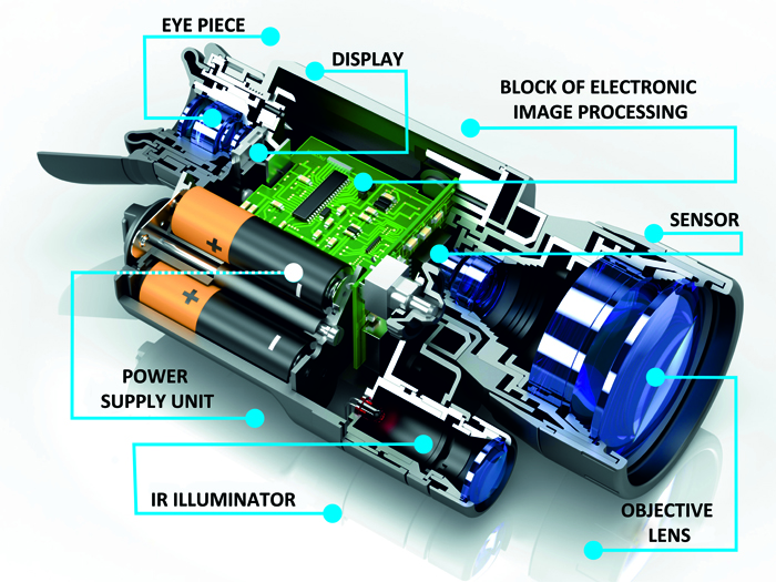
The power supply of digital night vision devices is provided by replaceable power elements: rechargeable batteries of the same size or integrated rechargeable batteries. Devices can be equipped with a socket for obtaining power from external sources (e.g. car power grid, compact external rechargeable batteries).
For work in low-light conditions, digital night vision devices are often equipped with integrated infrared illuminators based on laser diode or LED. For increased usability digital night vision devices can include a remote control system with major functions – in this case the user can control the device with the help of remote control (RC).
Digital devices can be equipped with rails for mounting on weapons.
As in any optic observation device, the objective lens is meant for projecting images onto the surface of the sensor, which in turn transforms reflections from the light of the object into an electric signal.
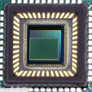
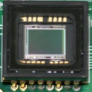
As a light-sensitive element, digital night vision devices utilise CCD or CMOS sensors.
 |
 |
|
CMOS SENSOR
|
CCD SENSOR |
Usually the electronic processing block consists of one or several boards (depending on the configuration of the device), on which are placed specialised circuits that process the signal that is obtained from the sensor and further transmit the signal to the display where the image of the observed object is shaped. Boards contain major device controls, and they also contain power supply circuits for the whole unit and for separate circuit elements.
Owing to the fact that digital night vision devices utilise micro-displays, in order to observe the image, it is necessary to use an eye piece that operates as a magnifying glass and allows users to view the magnified image.
The most often used displays in digital night vision devices are LCD displays of a transmissive type (where the display is lit up from the back side) or OLED displays (when electric current is applied its substance starts to emit light).
The application of OLED displays provides a series of advantages: the ability to use the device in lower temperatures, higher brightness and contrast of images and a simpler and more reliable construction (backlight sources as in LCDs are not present). Apart from LCD and OLED displays, digital devices can use micro-displays manufactured according to LCOS (Liquid Crystal on Silicone) technology – a type of reflective display.
In contrast to night vision devices based on image intensifier tubes (analogue), digital night vision devices allow a larger quantity of user adjustments and functions to be implemented. For example, brightness adjustment, image contrast, image colour selection, additional information in the field of view (current time, battery charge indication, icons of activated modes etc.), additional digital zoom, “Picture in Picture” function (shows, in a separate small window, an additional image of the whole object or its separate part including a magnified image) and temporary display deactivation (for energy-saving purposes and for masking an observer at the expense of absence of illumination from the operating display).
For saving images of observed objects, digital night vision devices may incorporate video recorders that allow photos and videos to be made.
In digital devices it is easy to implement such functions as wireless connection (e.g. Wi-Fi) data transmission (photo video) to external receivers, the integration of laser rangefinders (data from the range finder can be introduced into the field of view) and GPS-sensors (the ability to establish the co-ordinates of the observed object).
One advantage of digital night vision devices is the ability to work in daylight conditions without fear of flashes of light or intensive light sources which may damage night vision devices based on the image intensifier tube.
The reticle in digital riflescopes is as a rule is also digital, which means that the image of the reticle during the video signal processing is overlaid on the image on the screen and moved electronically, avoiding the necessity of mechanical parts for making ballistic corrections. These mechanical parts are often used in analogue night vision and daylight riflescopes and demand high precision during the manufacturing and assembling process.
Additionally, it avoids typical optic or night vision riflescope effects such as parallax, due to the fact that the observed image and the image of the reticle are located in the same plane – in the plane of display.
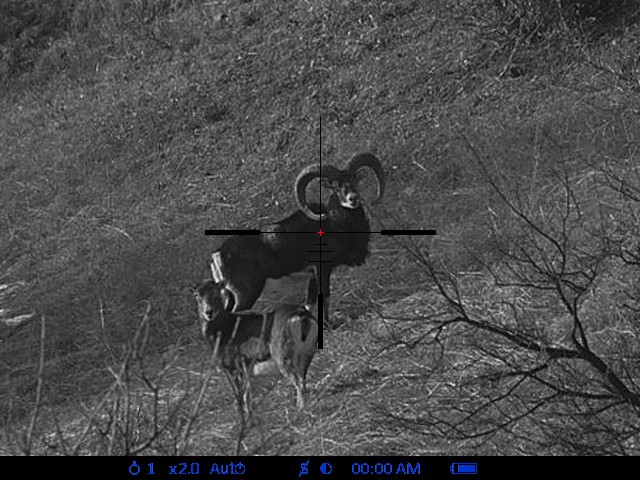
Digital riflescopes can keep a large quantity of reticles of different configurations and colors in its memory, providing the possibility of quick and easy “one shot zeroing” or “freeze zeroing”, the function of automatic ballistic reticle corrections in the course of alternating shooting distance, saving zeroing co-ordinates for several weapons, indicating weapon side incline or elevation angle, etc.
MAIN PARAMETERS OF DIGITAL NIGHT VISION DEVICES
- Magnification
- Resolution
- Sensitivity
- Angle of field of view
- Eye relief
- Power of the Infrared Illuminator
- Detection and recognition distance
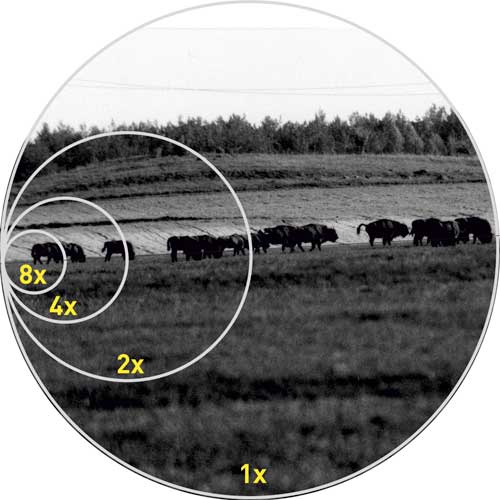
MAGNIFICATION
This parameter shows how many times the image of the object observed through the device exceeds the size of the same object observed with the naked eye.
Unit of measurement – time (notation «х», e.g., «2х» - «two times»).
For night vision devices, including digital, typical values of magnification range from 1х to 5х, because the main task of night vision devices is the detection and recognition of objects in low light conditions. Increase of magnification in night vision devices leads to significant reduction of total light-gathering power – the image will be much darker than in any similar device with smaller magnification.
The decline of light-gathering power because of the magnification increase can be compensated by the increase of the objective lens diameter, but this will in its turn lead to the increased size and weight of the device, reducing the overall convenience of handheld night vision devices (esp. riflescopes, as their users additionally have to hold weapons).
Magnification is defined by the focal distances of the objective lens and eye piece as well as by the scaling coefficient (К), which equals the ratio of physical sizes (diagonals) of display and sensor:
M= (fo/fe)*К= (fo/fe)*(Ld/Ls), where
fo – focal distance of objective lens
fe – focal distance of eye piece
Ls – size of sensor’s diagonal
Ld – size of display’s diagonal
Relation
The larger the focal distance of objective, size of display, the larger the magnification.
The larger the focal distance of eye piece, size of sensor, the smaller the magnification.
RESOLUTION
Resolution is the ability of the device to show two points or lines located close to one another separately. In technical references, this parameter can be indicated as “resolution”, “resolution limit” or “maximal resolution”. In principle it has the same meaning. Usually resolution is indicated in lines per millimeter (lpm) but it can also be indicated in angular units (seconds or minutes).
The bigger is the value of resolution in lines per millimeter and the smaller the value in angular units the higher the resolution. The higher the resolution, the clearer image the observer can see.
For night vision devices it is advisable to have a resolution no less than 25 lpm – such resolution allows the figure of a man to be distinguished from that of an animal or other object similar in size at a distance of 100m.
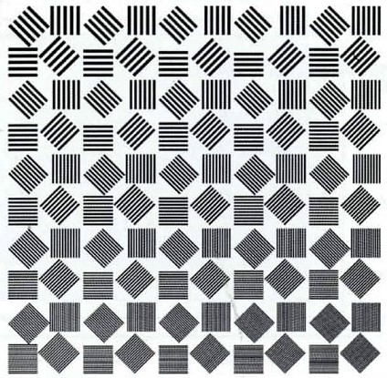
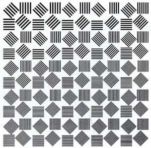
For measuring the resolution of night vision devices, a special equipment called a collimator is used. A collimator allows the creation of an imitation image of a special test-object – an illuminated line test chart that is located at a certain distance (usually at 100m).
 |
|
Line test chart
|
After looking at the image of the test-object through the device a conclusion can be made about the resolution of night vision equipment – the smaller the lines of the test chart that can be seen clearly separated from one another the higher the resolution.
 |
 |
| Normal resolution |
Low resolution |
Resolution is defined by the parameters of optic elements of device, sensor, display, quality of electronic circuitry solutions implemented in the device and also by the algorithms of signal processing.
The overall resolution of the unit depends on the parameters of the objective lens. Other things being equal, the bigger the diameter of the objective lens, the bigger its magnification and light-gathering power and the more small details it will be possible to see.
Resolution depends on the resolution of the objective lens and eyepiece. The objective lens creates the image of an object on the plane of the sensor and if the resolution of the objective lens is insufficient further improvement of the device’s resolution is impossible. In the same way a low quality eyepiece is able to deteriorate the clearest image created on the display by other components of the device.
Sensor characteristics exert a large influence on the unit’s resolution. First of all, it’s the sensor’s resolution – the quantity of pixels (usually indicated as a product of pixels in a line and in a column) and their size.
Relation:
The larger the quantity of pixels and the smaller their size the higher the resolution.
This statement is fair if sensors have identical physical size. Sensor with larger pixel density on a unit of surface have higher resolutions.
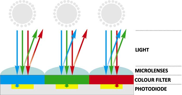
Unlike black and white sensors, the resolution of colour sensors in general will be smaller by 30-40%, which is caused by a different pixel structure – one pixel of a colour sensor consists of a combination of three subpixels, each of which registers the light only of a certain part of the spectrum (respectively - red, blue, green). It is achieved at the expense of the application of coloured light filters, letting through the light of only one colour. Thus when monochrome light hits the pixel of a colour camera, the signal will be registered by one subpixel only, while in black and white sensors the signal will be registered by each pixel the light hits. This is one of the reasons why the application of colour sensors in night vision devices is limited and often not rational.
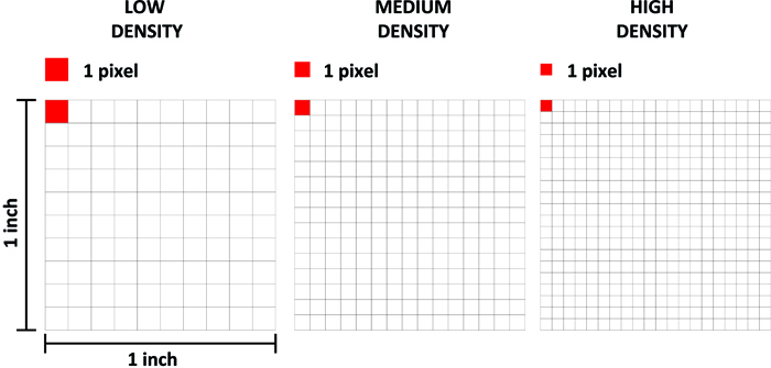
A unit’s resolution also depends on the parameters of display which shows the image. As with the sensor, the defining role here belongs to the display’s resolution (the amount of pixels) and the pixels’ size. The density of pixels in the display is described by PPI ("pixels per inch") – this characteristic defines the number of pixels that are located in one square inch of the display.
In the case of the direct image transfer (without scaling) from the sensor to the display, the resolutions of both parts would be the same. In this case the decrease of the device’s resolution is eliminated (the resolution decrease happens when the resolution of the display is lower than the resolution of the sensor) and there is no need to apply an expensive display (the display’s resolution is higher than the resolution of the sensor). When sensor produces signal in standard analogue TV format (e.g. PAL (625 lines in a frame) or NTSC (525 lines in a frame)) the use of a sensor with a higher resolution than resolution of the TV-signal format becomes unreasonable.
Digital night vision devices can use different algorithms for useful signal processing which can influence the overall resolution of the device. First of all, one can speak of “digital zooming” when the sensor image is processed digitally and transferred to the display with a certain magnification. In this case the overall resolution of the device is decreased. A similar effect can be observed in digital cameras during “digital zooming”.
The resolution of the device is also influenced by “Binning” (an algorithm that increases the sensitivity of the device by means of summoning signals from several neighbouring pixels which results in the proportional decrease of resolution).
Along with the earlier factors, it is necessary to mention several other factors which can lower the device’s resolution. These are noises of different kinds that distort useful signal and in the end worsen the image quality. It is possible to distinguish the following kinds of noise:
Photon noise. The result of the discrete nature of light. Photons of light fall on the photosensitive sensor’s surface in a way that is not simultaneous and not uniform in space.
Dark current noise (“snowfall noise”). If the device’s objective lens is covered by a lightproof lid, it will be possible to see “dark” frames on the display. The main reason for this noise is thermoionic emission of electrons (the spontaneous emission of electrons as the result of heating the sensor). The lower the temperature the lower the dark current signal that means smaller noise.
Transfer noise. During the transfer of charge inside the sensor a certain part of electrons that make up a useful signal is lost. They are grabbed by defects and impurities that are present in the sensor’s crystal.
Readout noise. When the signal accumulated in a pixel is taken out of the sensor, turned into a voltage and amplified, each element acquires additional noise called readout noise.
For reducing noise digital devices apply different software algorithms of image processing which are often called noise reduction algorithms.
Apart from noise, electric interferences resulting from mistakes in configuration of internal parts (the position of electronic boards, the connection of wires and cables inside the device) or from mistakes in board layouts (the position of conducting ways, the presence and quality of shielding layers) can significantly lower resolution. Interferences can be caused by mistakes in a device’s electric circuit: the wrong choice of elements for creating different filters and for power supply of electric circuits. That is why electric board designing, signal processing software coding and creating electric board layouts are important and difficult challenges when designing digital night vision devices.
Image resolution of digital night vision devices depends on the conditions of observation. The higher the illumination level of the observed object the clearer image we will see in the device. Thus a conclusion can be made that the maximal resolution of a digital night vision device will be achieved in almost daylight conditions or with the help of a powerful IR illuminator.
SENSITIVITY
In order to characterise the sensitivity of digital video cameras, they often use the parameter of minimal illuminance level on the observed object when the device is still able to produce an image.
This definition is the most suitable for digital devices operating in the visible range of the spectrum. For visible ranges a unit of sensitivity measurement is a light unit – “lux”.
Since digital devices are supposed to operate during the night, when the infrared spectrum prevails, in order to characterise their sensitivity it is more correct to use energy units that describe light flux.
Thus the parameter of sensitivity of digital night vision devices can be described as the minimal value of power of infrared light that enters the digital night vision device when the device is still able to produce an image with a resolution that provides recognition of the observed object (conforms to a resolution of 25 lpm).
Apart from that there is also parameter of spectral sensitivity – minimal power on the given wavelength of the infrared spectral range. When spectral sensitivity is indicated it also indicates the wavelength of light at which this value was achieved.
In contrast to illuminance in the visible range of spectrum, illuminance in the infrared range is impossible to measure in lux. In this case it is reasonable to use a universal unit of measurement – watt.
The sensitivity of a device depends on the following parameters:
- Light-gathering power and quality of objective lens
- Sensor parameters – physical size, its type and sensitivity
- Display parameters – brightness and contrast, resolution
- Algorithms for signal processing
- Quality of electric circuitry solutions implemented in the device
For obtaining high sensitivity in digital night vision devices it is necessary to collect all photons of light entering the objective lens and transfer them without losses onto the light sensitive surface of the sensor. An important role in the process of transferring belongs to the objective lens and its parameters such as light-gathering power, the amount of lenses in an optic scheme, the quality of antireflection coating on the lenses and the presence of blackening on the lens’s butts (in order to avoid dispersion of light inside the objective).
Relations:
The higher the light-gathering power of the objective lens (increases when the entrance pupil is increased and the focal distance is decreased), the higher the overall sensitivity of the device.
The more lenses that are used in the objective, the smaller the light-gathering power and the sensitivity of the device.
The higher the optical transmission coefficients of lenses constituting the objective, the higher the sensitivity.
The sensor is the main receiver and converter of light into electric signal. It is the sensor that to a great extent defines the sensitivity of a device. The sensitivity of the sensor depends on the pixels’ size and their density on the sensor. Other things being equal, the bigger the size of pixel the higher the sensitivity of the sensor. The smaller the correlation of the total area of the sensor to the total area of all pixels, the higher the overall sensitivity of the sensor.
Recently many manufacturers of cheap night vision devices started using cheap sensors for photo cameras (often colour sensors). These sensors have good sensitivity in visible (daylight) range of the spectrum, but very low sensitivity in the infrared range. Technical descriptions of such devices lack any information about sensitivity but proudly state a large amount of megapixels. It is easy to conclude that despite the high sensor resolution such devices are not able to produce quality images at nighttime without a powerful illumination source because its sensor has a low sensitivity in the infrared range of the spectrum.
The second common mistake is when the sensitivity of digital night vision devices is indicated in photometric units (lux). Here values of sensitivity can reach a ten thousandth fraction of lux, which is significantly higher than analogue night vision devices that are based on image intensifier tubes generation 2+ or higher can provide. Such supernatural sensitivity can be explained in a simple way. As a rule, for sensitivity measurement a luxmeter is used, its spectral characteristic coincides with the spectral characteristic of the human eye (see diagram). Just as a human eye, the luxmeter is able to perceive (measure) illumination only in the visible range of the spectrum from 380 nm to 780 nm. It means that when measuring illumination in the night with the help of a luxmeter, obtained values of illumination will be close to zero because in the night the visible range of illumination is practically absent. But on the other hand, strong infrared illumination is present (see diagram of natural illumination of the night sky), and the luxmeter is unable to register it, whereas night vision devices can easily register this illumination. As an example the diagram shows spectral sensitivity graphs of SONY CCD sensors and generation 2+ image tube intensifiers.
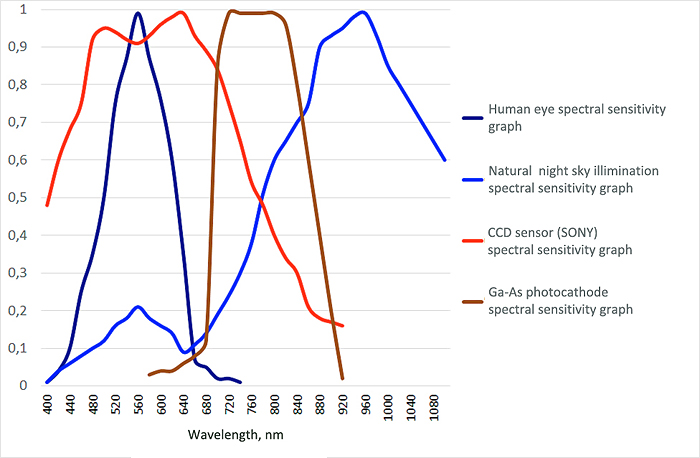
Spectral sensitivity is used as a parameter which characterises the ability of a night vision device to work confidently in the night. As a rule, it is indicated on one or several wavelengths of the spectral range. To understand the “quality” of digital night vision devices the most optimal way is to have information about spectral sensitivity at such wavelengths as e.g. 780 … 810 nm (the average value of infrared illumination of stellar sky; in this range sensors have average sensitivity) and 910 … 940 nm (high value of infrared illumination of stellar sky; invisible infrared range, sensors are still able to be sensitive).
Comparing the values of spectral sensitivity in several digital devices it is possible to make certain conclusions about their ability to “see” in the night. Here one should remember that the sensitivity of a digital device is defined not only by the sensitivity of its sensor but also on such parameters and characteristics of the device as the resolution of the objective lens and eye piece, display resolution, light-gathering power of the objective lens, sensor quality (absence of noise), quality of circuitry solutions (absence of interferences) and applied algorithms of signal processing.
Contemporary digital night vision devices use two main types of sensors – CCD and CMOS. The major difference between these two types lies in the electronic organisation of signal readout from the pixels. In CCD (Charge Coupled Device), signals from every pixel are transferred sequentially to the sensor’s electronics and then the amplification of the overall signal takes place. In CMOS (Complementary Metal-Oxide Semiconductor), signals from all pixels are read simultaneously and amplified by means of amplifiers individually for each pixel. For this reason, (the necessity of having part of the sensor used by a large quantity of individual amplifiers) the density of pixels in CMOS sensors is lower than in CCD sensors and respectively their sensitivity is also lower. In the last few years, new technologies have appeared for CMOS sensor manufacturing (such as EXMOR SONY, BSI (Toshiba, Omnivision)) focused on increasing the density of pixels on the sensor’s surface which leads to an increase in the overall sensitivity of the sensor. Parameters for such sensors have come close to reaching the figures of CCD sensors and the best samples surpass them in certain parameters.
A night vision unit’s display also influences the overall sensitivity of the device, first of all at the expense of its resolution and contrast/brightness values.
It is possible to make certain conclusions about how digital night vision devices will operate if compared to night vision devices based on generation 2+ or 3 image intensifier tubes. On the sensitivity diagram it is clearly shown that CCD sensors and photocathode of image tube intensifiers of 2+/3 generation have better sensitivity in the infrared range 750-850 nm and worse in ranges higher than 900nm.
Comparing these data with the graph of spectral spread of natural night illumination it is possible to conclude that in passive mode (without auxiliary infrared light) the advantage (higher sensitivity) in the night will be on the side of night vision devices based on image intensifier tubes of the 2+/3 generation.
The important thing here is that in the range higher than 900 nm digital night vision devices still have a certain sensitivity (when the wavelength increases, sensitivity decreases gradually) at the same time the sensitivity of night vision devices based on image intensifier tubes of 2+/3 generation decreases quickly to zero. For this reason, night vision devices based on image intensifier tubes are ineffective when used with “invisible” infrared illuminators (e.g. 915 nm or 940 nm), whereas digital night vision devices are highly compatible with them. Due to the fact that analogue night vision devices (esp. gen 2+) often require additional illumination when used outside the city (e.g. for hunting), a factor of compatibility with invisible infrared illuminators becomes a substantial advantage of digital night vision devices.
In the context of this topic, sensitivity is a minimal value of power of infrared radiation. That is why the less its numeric value in watts the better its sensitivity.
For comparison purposes we shall look at measured values of sensitivity for Yukon and Pulsar night vision devices (see table) at a 780 nm wavelength. Digisight N750 at a wavelength of 780 nm will be much more sensitive than NVMT Spartan 3x42, but less sensitive than Phantom 3x50 generation 2+. At 915nm wavelength Digisight N750 will already have an advantage over Phantom 3x50 generation 2+.
| Night vision device |
Generation |
Spectral sensitivity
at 780nm, mW |
Spectral sensitivity
at 915nm, mW |
| Digisight N750 |
Digital |
≈2,5·10 -5 |
≈1,2·10 -4 |
| Phantom 3x50 |
II+ |
≈1,5·10 -5 |
≈5·10 -4 |
| Spartan 3x42 |
I |
≈25·10 -5 |
≈8000·10 -4 |
| Spartan 4x50 |
I |
≈15·10 -5 |
≈2500·10-4 |
FIELD OF VIEW
This parameter characterises the size of space that can be observed simultaneously through the device. Usually in technical specifications the field of view is indicated in degrees (the field of view angle is indicated in the picture below as 2Ѡ) or in metres for some known distance (L) to observed object (linear field of view indicated in the picture below as А).

The field of view of digital night vision devices is defined by the focal distance of the objective lens (fob) and by the physical size of the sensor (В). Usually for calculations of field of view the width (horizontal size) of the sensor is taken, and the results show an angular horizontal field of view:
2Ѡ=2*arctg(B/(2* fo))
Knowing the vertical size of the sensor (height) and the diagonal size it is possible to calculate the angular vertical and diagonal field of view.
Relation:
The larger the size of the sensor or the smaller the focal distance of objective lens the greater the field of view angle.
The greater the field of view of the device the more convenient it is to observe objects – there is no need for constant movements of the device in order to view the necessary part of space.
It is important to understand that field of view is inversely proportional to magnification – increasing the magnification of the device leads to shrinking the field of view.
At the same time when field of view increases, detection and recognition distances will decrease because first of all magnification will decrease and secondly if the infrared illuminator is used for comfortable observation it will be necessary to use the infrared illuminator with a wide annular divergence of beam (it should approximately correspond to the angular field of view). This will in its turn lead to a decrease of luminance in respect to the surface and will lead to a decrease of the infrared illuminator’s distance.
EYE RELIEF
Eye relief is the distance from the external surface of the last lens of the eye piece to the plane in which the observer’s eye is located when the observed image is optimal (the largest possible field of view, minimal distortions). This parameter is very important for weapon sights, where eye relief should be at least 50 mm (optimal 80-100 mm). Such big values of eye relief are necessary to avoid injury to the observer because of the recoil during the shot. In night vision devices eye relief as a rule equals the length of eye shade which is necessary to mask illumination of the image intensifier tube or screen.
DETECTION AND RECOGNITION DISTANCE
Detection distance – the maximal distance from the observation device to some object (usually man) which may be detected with the help of the device.
Recognition distance – the maximal distance at which the observer can recognise the type of observed object (human, animal, building, etc.).
These values are not constant for a specific device and depend on the following parameters:
- Magnification
- Resolution
- Sensitivity of device
- Observation conditions
- Characteristics of the observed object
- Contrast level between object and background
- Use of an infrared illuminator
Devices that have greater magnification (other things being equal) allow viewed objects to be brought closer and respectively the detection and recognition distance will be greater in such devices.
The resolution of the device influences to a great extent the recognition distance – high resolution devices allows the observer to more confidently recognise the type of observed object thanks to the clearer image of the object’s details.
The sensitivity of digital night vision devices influences detection and recognition distance in the same way. Devices with better sensitivity ensure clearer and more contrasting images of the observed object at larger distance than devices with less sensitivity.
Apart from the device’s parameters, detection and recognition distance is influenced significantly by observation conditions and the characteristics of the observed object. Observation conditions will be defined by the level of natural night sky illumination and by the transparency of the atmosphere. If illumination levels and transparency of the atmosphere decrease (smoke, fog, dust particles, etc.) detection and recognition distances will also decrease.
The object’s reflecting properties will influence detection and recognition distances in the same way; they will be defined by colour and texture (glossy or opaque) of the object’s surface and also by the level of contrast of the object compared to the background. For instance, it is easier to detect and recognise an animal that is located on the background of a snow field than on the background of a forest edge, green grassland or field.
In low-light conditions the detection and recognition distance can be increased with the help of infrared illuminators. Apart from increasing the overall illuminance of the object, in some cases the infrared illuminator’s radiation is well reflected in an animal’s eyes, resulting in the fact that the animal can be detected at quite long distances – during observation through night vision device its eyes will be seen as bright spots.
IR ILLUMINATORS
It is worth mentioning the application of IR illuminators together with digital night vision devices. Usually night vision devices have integrated IR illuminators. At the same time on the market there is a large quantity of IR illuminators sold as accessories which are intended for combined use with night vision devices.
Based on the type of emission source, IR illuminators can be divided into two main groups – LED illuminators and laser illuminators.
In LED illuminators a semiconductor diode is used; it emits radiation at a certain wavelength of infrared range. On the market it is possible to find LED illuminators with different wavelengths (most often 805 nm, 850 nm and 940 nm) and with different power.
Laser illuminators are manufactured on the basis of laser semiconductor diodes. With respect to LED illuminators laser illuminators have significant advantages.
First of all, their radiation is coherent, meaning that all photons of light in a beam have the same energy, direction and wavelength. Due to this a beam of light has a high-energy density in a narrow spectral range, which preserves even at long distances. LEDs have dispersed radiation which is characterised by a wide spectral range and large energy losses at the distance from radiation source. It means that having equal power, the laser illuminator is able to illuminate the observed object at longer distances than the LED illuminator; in other words, the “operation distance” of the laser illuminator is greater than of the LED illuminator.
Second, energy consumption in laser illuminators is significantly lower than in LED illuminators with the same power.
The main parameters of illuminators are radiation power and annular divergence of beam.
Radiation power is the main defining factor for the distance of an IR illuminator. It depends on the type of source, optic scheme and the quality of the lenses and anti-reflecting coating. In the majority of LED illuminators, the maximal radiation power ranges from 30 to 100 mW (low values of power in integrated IR illuminators, higher values in detachable illuminators produced as accessories).
In laser illuminators maximal power can fluctuate from 10 to 50 mW having approximately the same energy consumption as LED illuminators.
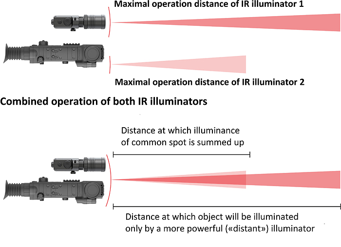
If several illuminators are used simultaneously (e.g. integrated and detachable external illuminators) the overall illuminance of a spot will be summed up, but only in cases when the observed object is at the distance not exceeding the maximal distance of operation of each of these two illuminators (meaning that each of the illuminators is able to light up the observed object at this distance). If the distance to an object will exceed the maximal operation distance of one of the illuminators then the observed object will be illuminated only by one illuminator, which is more powerful. That means that at this distance there will be no summing up of illuminance spots.
To the disadvantage of laser illuminators, one can attribute certain dangers they produce for the human eye during direct viewing in cases when radiation exceeds the 1-st class of laser safety. For this reason, in the majority of countries only illuminators of the 1-st class of laser safety (totally safe) are allowed on the civil market. This fact to a great extent deters the wide spreading of laser illuminators.
Correctly designed 1-st class laser illuminators surpass ordinary LED illuminators in operation effectiveness because having relatively equal values of operation distance they have a smaller size and consume less energy.
The annular divergence of a beam of an IR illuminator must be close to the angular field of view of a night vision device in order to illuminate the total area that can be seen through the device. The larger the annular divergence the lower the illuminance on the area and respectively the illuminance distance is smaller. In practice IR illuminators have an uneven spread of energy (illuminance) on the area of the spot. As a rule, the central area of the spot has a larger energy than the area closer to the edges. In fact, it means that if the annular divergence is increased the user will notice to a great extent the decrease of illuminance in the area close to edges of the spot, while at the same time the central area will be illuminated more intensively.
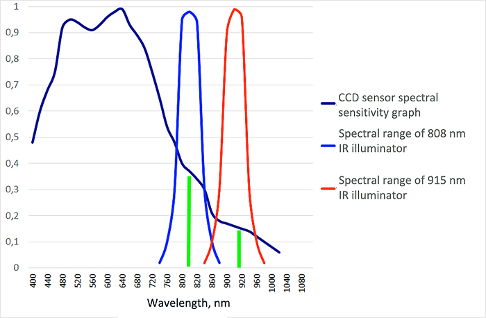
When selecting an IR illuminator for a night vision device it is necessary to take into account the spectral range in which the night vision device operates. Maximal effectiveness (illumination distance) will be in the illuminator with a wavelength at which the night vision device has the highest sensitivity. For instance, when an IR illuminator with an 808 nm wavelength is used, digital devices will have better vision than with a 940 nm wavelength, meaning that the sensitivity of the sensor at 808 nm is higher.
It is worth mentioning one more advantage of digital night vision devices when they are used in combination with IR illuminators. Obviously if compared to image intensifier tubes, sensors of digital devices have lower overall sensitivity, but significantly higher spectral sensitivity in ranges of 900 nm and higher. Radiation in this range is already invisible to human and animal eyes. All this allows the successful application of invisible range IR illuminators for additional illumination of observed objects in combination with digital night vision devices. At the same time this invisible IR illuminator will be practically useless in combination with analogue night vision devices. This is especially true when digital night vision devices are used for hunting: hunters can confidently use “invisible” illuminators for additional illumination – the animal does not see it and does not get scared.
The influence of power of IR illuminators and their type on recognition distance depending on a device’s sensitivity is shown in table 1 (for laser illuminators) and table 2 (for LED illuminators).
Data is given for the following conditions: moonless night, cloudy sky, transparent atmosphere (no fog, no haze). As an observation object a man-sized human figure was used in camouflage clothes located on the background of the forest edge. The annular divergence of a beam of IR illuminators is 5-7 degrees.
Table 1
|
Sensitivity at
780 nm wavelenth, mW
|
Laser 780 nm
|
Sensitivity at
915 nm wavelenth, mW
|
Laser 915 nm
|
|
Recognition distance, m
|
Recognition distance, m
|
|
10 mW
|
20 mW
|
50 mW
|
10 mW
|
20 mW
|
50 mW
|
|
400·10-5 - 500·10-5
|
40-50
|
60-75
|
90-110
|
100·10-4 - 150·10-4
|
30-40
|
50-60
|
70-80
|
|
150·10-5 - 200·10-5
|
60-80
|
80-100
|
120-140
|
35·10-4 - 50·10-4
|
50-70
|
70-90
|
100-120
|
|
25·10-5 - 70·10-5
|
100-120
|
125-160
|
170-220
|
15·10-4 - 30·10-4
|
80-90
|
90-110
|
140-160
|
|
15·10-5 - 20·10-5
|
130-150
|
170-190
|
230-270
|
6·10-4 - 10·10-4
|
100-120
|
130-150
|
180-200
|
|
6·10-5 - 10·10-5
|
160-180
|
210-230
|
280-320
|
4·10-4 - 5·10-4
|
130-160
|
160-180
|
210-230
|
|
1·10-5 - 5·10-5
|
200-260
|
280-320
|
380-440
|
1·10-4 - 3·10-4
|
170-220
|
190-240
|
250-300
|
Table 2
|
Sensitivity at
780 nm
wavelength, mW
|
LED 805 nm
|
LED 850 nm
|
Sensitivity at
915 nm
wavelength, mW
|
LED 940 nm
|
|
Recognition distance, m
|
Recognition distance, m
|
Recognition distance, m
|
|
20 mW
|
50 mW
|
100 mW
|
20 mW
|
50 mW
|
100 mW
|
20 mW
|
50 mW
|
100 mW
|
|
400·10-5 - 500·10-5
|
35-45
|
60-80
|
120-140
|
20-30
|
50-70
|
80-110
|
100·10-4 - 150·10-4
|
20-25
|
40-60
|
70-90
|
|
150·10-5 - 200·10-5
|
50-60
|
90-110
|
150-180
|
40-50
|
80-90
|
130-150
|
35·10-4 - 50·10-4
|
30-40
|
60-80
|
110-140
|
|
25·10-5 - 70·10-5
|
70-80
|
120-140
|
210-250
|
60-70
|
110-120
|
170-200
|
15·10-4 - 30·10-4
|
50-60
|
90-100
|
150-170
|
|
15·10-5 - 20·10-5
|
85-90
|
150-160
|
270-300
|
80-90
|
130-140
|
210-220
|
6·10-4 - 10·10-4
|
65-70
|
120-130
|
190-210
|
|
6·10-5 - 10·10-5
|
100-110
|
170-190
|
310-340
|
100-110
|
160-180
|
240-280
|
4·10-4 - 5·10-4
|
80-90
|
140-160
|
220-250
|
|
1·10-5 - 5·10-5
|
120-150
|
210-260
|
350-380
|
120-160
|
190-240
|
300-350
|
1·10-4 - 3·10-4
|
100-130
|
170-200
|
|
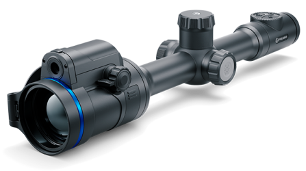
 Thermion 2 LRF XL50
Thermal Imaging Riflescope
Thermion 2 LRF XL50
Thermal Imaging Riflescope
 Thermion 2 LRF
Thermal Imaging Riflescopes
Thermion 2 LRF
Thermal Imaging Riflescopes
 Talion
Thermal Imaging Riflescopes
Talion
Thermal Imaging Riflescopes
 Thermion 2
Thermal Imaging Riflescopes
Thermion 2
Thermal Imaging Riflescopes
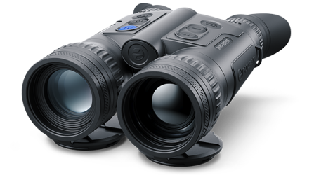
 Merger LRF XL50
Thermal Imaging Binoculars
Merger LRF XL50
Thermal Imaging Binoculars
 Merger LRF XP50
Thermal Imaging Binoculars
New
Merger LRF XP50
Thermal Imaging Binoculars
New Merger LRF XP35
Thermal Imaging Binoculars
Merger LRF XP35
Thermal Imaging Binoculars
 Merger LRF XQ35
Thermal Imaging Binoculars
New
Merger LRF XQ35
Thermal Imaging Binoculars
New Telos
Thermal Imaging Monoculars
Telos
Thermal Imaging Monoculars
 Axion 2 LRF
Thermal Imaging Monoculars
Axion 2 LRF
Thermal Imaging Monoculars
 Axion 2
Thermal Imaging Monoculars
New
Axion 2
Thermal Imaging Monoculars
New Axion XQ30 PRO
Thermal Imaging Monoculars
Axion XQ30 PRO
Thermal Imaging Monoculars
 Krypton 2
Thermal Imaging Monocular
Krypton 2
Thermal Imaging Monocular
 Axion XM30F
Thermal Imaging Monoculars
Axion XM30F
Thermal Imaging Monoculars
 Pulsar Digex-XS
External Infrared Illuminators
Pulsar Digex-XS
External Infrared Illuminators
 APS Batteries
Battery Packs
APS Batteries
Battery Packs
 APS Chargers
Battery Chargers
APS Chargers
Battery Chargers
 LPS 7i Battery Pack
Battery Packs
LPS 7i Battery Pack
Battery Packs
 Telos LRF Tripod Adapter
Pulsar Accessories
Telos LRF Tripod Adapter
Pulsar Accessories
 IPS Batteries
Battery Packs
IPS Batteries
Battery Packs
 IPS Battery Charger
Battery Charger
IPS Battery Charger
Battery Charger
 Rifle Mounts
for Pulsar Riflescopes
Rifle Mounts
for Pulsar Riflescopes
 H7 Spacers
Repair Kits
New
H7 Spacers
Repair Kits
New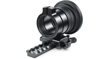 PSP-V Weaver Rail Adapter
Adapter
PSP-V Weaver Rail Adapter
Adapter
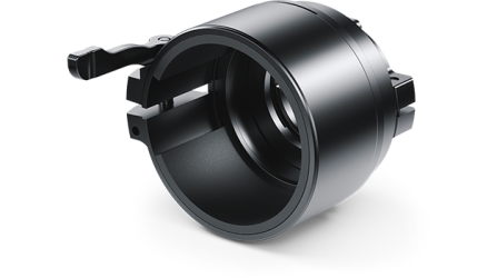 PSP Ring Adapters
Adapters
New
PSP Ring Adapters
Adapters
New PSP-B Ring Adapters
Ring Adapters
PSP-B Ring Adapters
Ring Adapters
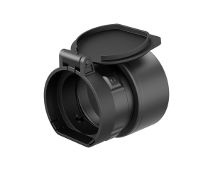 FN Adapters
Cover Ring Adapters
FN Adapters
Cover Ring Adapters
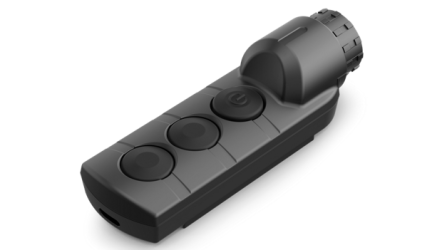 Remote Controls
for digital devices and thermal imagers
Remote Controls
for digital devices and thermal imagers
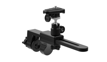 C-Clamp Mount
Pulsar Accessories
C-Clamp Mount
Pulsar Accessories
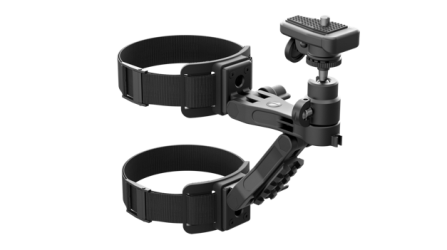 Tree mount
Pulsar Accessories
Tree mount
Pulsar Accessories
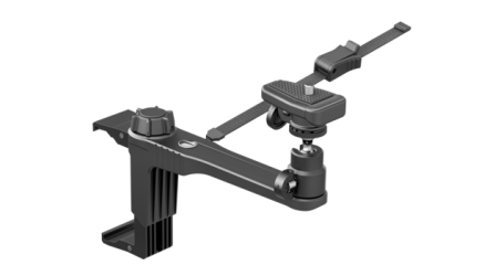 Window Frame Mount
Pulsar Accessories
Window Frame Mount
Pulsar Accessories
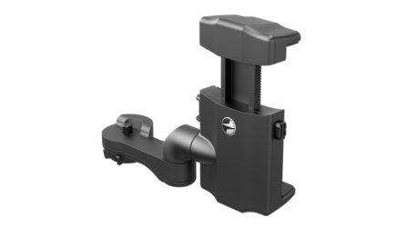 Helion Flip-Up Phone Mount
Pulsar Accessories
Helion Flip-Up Phone Mount
Pulsar Accessories
 Flat Glass Mount
Pulsar Accessories
Flat Glass Mount
Pulsar Accessories
 Neck Straps
Accessories
New
Neck Straps
Accessories
New Monocular Pulsar 3x20 B
Accessories
Monocular Pulsar 3x20 B
Accessories
 Thermal Zeroing Targets
Accessories
Thermal Zeroing Targets
Accessories


 English
 German
 French
 Spanish
 Italiano
 English
 Lietuvių